Overview
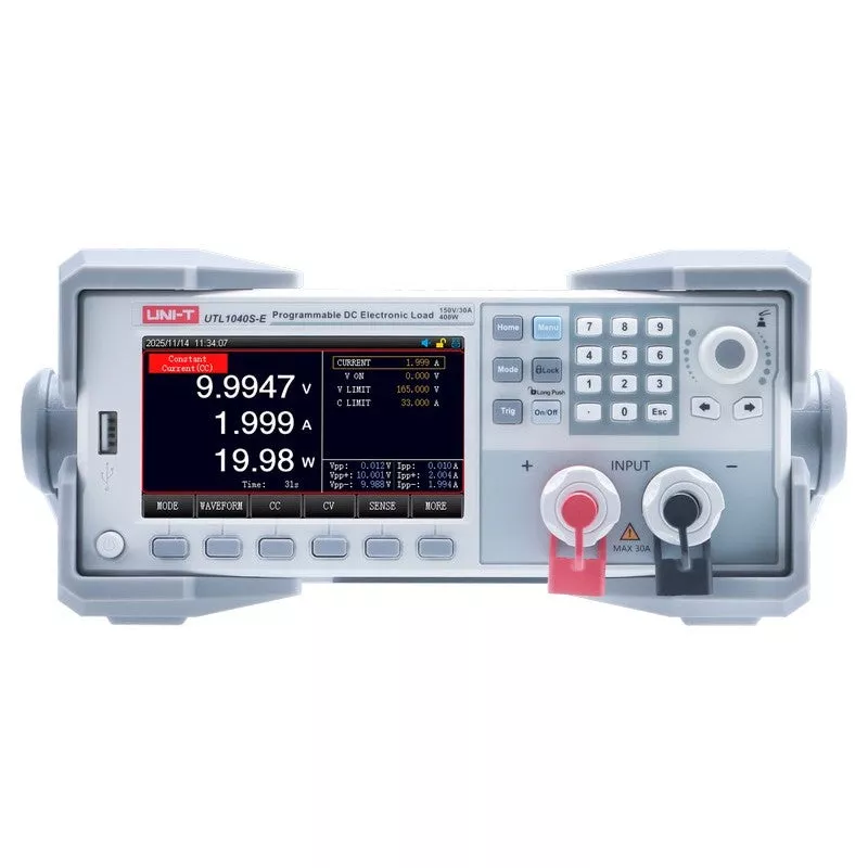
The UNI-T UTL1020S-E is a single-channel programmable DC electronic load rated 200 W, 0150 V, 030 A. It runs four constant modes CC, CV, CR, CP plus eleven additional test modes including dynamic, OVP, OCP, time, CR-LED, battery, automatic list, short-circuit, load-effect, combination, and list, for 15 test modes in total. Synchronous sampling reaches 500 kHz with high-performance DSP processing and a self-adaptive voltage and current waveform display on the 4.3-inch TFT LCD.
Dynamic mode pulls load at up to 50 kHz so current and voltage peaks Vpp and Ipp can be observed directly. The load also provides on-screen ripple measurement, a rear-panel Sense terminal for remote voltage compensation, and SCPI remote control over RS232 with a HANDLER interface and USB Host port for data logging and automated production test.
Choosing Your Model 200 W 15-Mode Load
Two 200 W models share the same load architecture, the same 15 test modes, the same accuracy class, and the same 0150 V / 030 A input envelope. They differ in one axis only: measurement resolution.
| UTL1020S (high-resolution) | Current resolution 0.01 mA / 0.1 mA, voltage readback 0.01 mV / 0.1 mV finer metering for precision readback work. |
| UTL1020S-E (standard resolution) | Same 200 W load, same 15 modes; current resolution 0.1 mA / 1 mA, voltage readback 0.1 mV / 1 mV. The lower-cost choice when fine readback resolution is not the deciding factor. |
This page describes the UTL1020S-E. Capability, test modes, protection, and interfaces below apply to both 200 W models; the Specifications table lists this model’s resolution figures.
Key Features
- 200 W, 0150 V, 030 A single-channel load CC, CV, CR, CP basic modes with dual high/low input ranges.
- 15 test modes CC, CV, CR, CP, dynamic, OVP, time, OCP, CR-LED, battery, automatic list, short circuit, load effect, combination, list.
- 500 kHz synchronous sampling high sampling density for accurate transient capture and reduced measurement omission.
- 50 kHz dynamic mode programmable rise/fall slope (0.00063 A/s) simulates real changing load conditions; Vpp / Ipp observed directly.
- Battery test with charge and discharge curves records both charge and discharge curves for battery characterization.
- Automatic list test up to 200-step programmable multi-mode sequences for automated, repeatable testing.
- On-screen ripple measurement and real-time waveform ripple readout in the screen corner; [WAVE] key shows live V/I waveform without an external oscilloscope.
- Remote compensation (Sense terminal) rear-panel Sense terminal eliminates lead voltage-drop error at high current.
- RS232 / USB Host / HANDLER, SCPI protocol PC software control, USB-drive screenshots and list import/export, HANDLER for ATE integration.
- Current resolution 0.1 mA / 1 mA, voltage readback 0.1 mV / 1 mV, 16-bit CR, 3 years standard + 2 year extension.
UNI-T UTL1020S-E Details
15 Test Modes for Power, Battery, and LED-Driver Validation
Four constant modes CC (constant current), CV (constant voltage), CR (constant resistance), CP (constant power) plus eleven more: dynamic, OVP, time, OCP, CR-LED, battery, automatic list, short-circuit, load effect, combination, and list. The CR-LED mode simulates real LED forward-voltage behavior for LED-driver testing; battery mode records charge and discharge curves; combination mode pairs two basic modes (CR+CC, CV+CR, CV+CC) for more realistic DUT conditions.
15 Test Modes for Power, Battery, and LED-Driver ValidationDynamic Mode 50 kHz Transient Load Simulation
Dynamic Mode 50 kHz Transient Load Simulation
Dynamic mode pulls load at frequencies up to 50 kHz with T1/T2 timing from 10 s to 50 s (1 s resolution) and a programmable rising/falling current slope of 0.0006 A/s to 3 A/s. The current and voltage peak waveforms are observed directly on screen with Vpp and Ipp measurement, so transient response and overshoot of the device under test can be characterized without a separate oscilloscope.
Battery Test with Charge and Discharge Curves
Battery mode performs constant-current or constant-power discharge testing and records the full discharge curve. The UTL1020S-E captures both the discharge and the charging curve, so capacity, internal-resistance behavior, and cycle characteristics are traceable from a single instrument useful for battery-pack, BMS, and power-bank validation.
Battery Test with Charge and Discharge CurvesAutomatic List Test 200-Step Programmable Sequences
Automatic List Test 200-Step Programmable Sequences
The automatic list test runs editable multi-step, multi-mode sequences with up to 200 steps. Set the appropriate load value and mode for each step and the list executes the full test process automatically. List files save to internal memory or a USB drive and can be imported, so a validated production-test sequence transfers between units quickly.
On-Screen Ripple Measurement and Real-Time Waveform
Ripple is measured and displayed directly in the corner of the screen, replacing a separate oscilloscope measurement for routine power-supply ripple checks. Pressing the [WAVE] function key shows the live voltage and current waveform, with the self-adaptive display scaling automatically to the signal.
On-Screen Ripple Measurement and Real-Time WaveformOVP and OCP Protection Testing
OVP and OCP Protection Testing
Set the protection threshold according to the device under test and the UTL1020S-E measures the protection function and the protection response time. Overvoltage protection triggers with delayed protection at 152 V and immediate protection at 165 V; overcurrent protection at 30.3 A delayed and 33 A immediate; overpower at 202 W delayed and 220 W immediate. Instrument protection can also be turned off to prevent false alarms during characterization.
Load Effect Test
The load effect test automatically measures and calculates load-regulation results from the configured test values, so power-supply load regulation is characterized without manual point-by-point measurement and calculation.
Load Effect TestTime Test Rise and Fall Time of the Power Supply
Time Test Rise and Fall Time of the Power Supply
Time test measures the rise and fall times of the device under test against configured thresholds, with 1 s timing resolution and 100 ppm timing accuracy, for power-supply turn-on / turn-off and transient-timing characterization.
Applications
The 200 W 15-mode envelope CC/CV/CR/CP plus dynamic, battery, list, protection, load-effect, and combination modes with 500 kHz sampling covers R&D and production test for power electronics.
- Switching power-supply and adapter test load regulation, ripple, transient response, and protection-function verification from one instrument.
- Battery and battery-pack characterization charge and discharge curve recording for capacity, BMS, and cycle testing.
- LED-driver validation CR-LED mode simulates real LED forward-voltage behavior.
- Charger and power-bank testing automatic list sequences for repeatable multi-step production test.
- DC-DC converter and module test dynamic loading at up to 50 kHz to characterize transient overshoot and recovery.
- Automated production test (ATE) SCPI over RS232 plus HANDLER interface for test-line integration; list import/export for fast line setup.
Accessories and Family Options
Included with Every Unit
- AC power cord
- RS232 communication cable
- Plug-in terminal block (5.08-2P) and screw-free spring terminal block (2.54-6P)
- Spare fuse (2 pcs)
- Certificate of calibration and multi-language safety precautions
Optional Test Leads
- UT-L0615-OO double O-type terminal, 60 A / 1.5 m
- UT-L0320-UU double U-type terminal, 30 A / 2 m
- UT-L0312-UU double U-type terminal, 30 A / 1.2 m
- UT-L0110-BB double fold-insert, 10 A / 1 m
- UT-L0110-BU fold-insert to U-type, 10 A / 1 m
UTL1000S Series
Four models share the same chassis, 15 test modes, 500 kHz sampling, accuracy class, and 0150 V / 030 A input envelope:
- UTL1020S 200 W, high-resolution
- UTL1020S-E 200 W, standard resolution (this product)
- UTL1040S 400 W, high-resolution
- UTL1040S-E 400 W, standard resolution
Frequently Asked Questions
What is the difference between the UTL1020S-E and the UTL1020S?
Both are 200 W loads with the same 15 test modes, the same accuracy class, and the same 0150 V / 030 A input envelope. The difference is measurement resolution: the UTL1020S-E resolves current to 0.1 mA / 1 mA and voltage readback to 0.1 mV / 1 mV across its low and high ranges. The high-resolution model is suited to precision readback work; the standard-resolution model is the lower-cost choice when fine readback resolution is not the deciding factor.
How many test modes does the UTL1020S-E have, and what are they?
15 modes: CC, CV, CR, CP, dynamic, OVP, time, OCP, CR-LED, battery, automatic list, short circuit, load effect, combination, list. The four constant modes (CC, CV, CR, CP) cover standard load testing; the remaining modes add transient, protection, battery, LED-driver, automated, and combination testing.
Can the UTL1020S-E test batteries?
Yes. Battery mode performs discharge testing and records both the discharge and the charging curve, so capacity and cycle behavior are traceable from the instrument useful for battery-pack, BMS, and power-bank validation.
Does it measure ripple without an oscilloscope?
Yes. Ripple is measured and displayed in the corner of the screen, and the [WAVE] key shows the live voltage and current waveform, so routine ripple and waveform checks do not require a separate oscilloscope.
What is the Sense terminal for?
At high current, lead resistance creates a voltage drop between the load and the device under test. The rear-panel Sense terminal measures voltage at the DUT output terminal directly (remote compensation), so the displayed voltage reflects the DUT rather than the voltage after the test leads.
How is the UTL1020S-E controlled remotely?
Over RS232 using the standard SCPI protocol with the included PC>15 Test Modes for Power, Battery, and LED-Driver ValidationDynamic Mode 50 kHz Transient Load SimulationBattery Test with Charge and Discharge CurvesAutomatic List Test 200-Step Programmable SequencesOn-Screen Ripple Measurement and Real-Time WaveformOVP and OCP Protection TestingLoad Effect TestTime Test Rise and Fall Time of the Power Supply
Specifications
| Input power (rated) | 200 W |
| Input voltage | 015 V (low) / 0150 V (high) |
| Input current | 03 A (low) / 030 A (high) |
| Minimum operating voltage | 1.4 V 0.1 V at 30 A |
| CV mode | Range 0.1150 V, resolution 1 mV, accuracy (0.03% + 0.05% FS) |
| CC mode | Resolution 0.1 mA / 1 mA (low / high), accuracy (0.03% + 0.05% FS) |
| CR mode | Range 0.05 10 k, resolution 16 bits, accuracy (0.1 + 0.01R)% |
| CP mode | Range 200 W, resolution 10 mW, accuracy (0.1% + 0.1% FS) |
| Readback voltage resolution (CC/CP) | 0.1 mV / 1 mV (low / high) |
| Readback voltage resolution (CV/CR) | 0.1 mV |
| Readback current resolution | 0.1 mA / 1 mA (low / high) |
| Readback accuracy (V / I / P) | (0.02% + 0.3% FS) / (0.03% + 0.05% FS) / (0.1% + 0.1% FS) |
| Dynamic mode T1 & T2 | 10 s 50 s, 1 s resolution; timing accuracy 1 s / 1 ms 100 ppm |
| Dynamic rise/fall slope | 0.0006 A/s 3 A/s (min. rise time 10 s) |
| Dynamic frequency | 50 kHz |
| Synchronous sampling | 500 kHz synchronous |
| Overpower protection | Delay 202 W, immediate 220 W |
| Overcurrent protection | Delay 30.3 A, immediate 33 A |
| Overvoltage protection | Delay 152 V, immediate 165 V |
| Over-temperature protection | 85 C |
| Short-circuit (CC / CV / CR) | 30 A / 0 V / 60 m |
| Test modes | 15: CC, CV, CR, CP, dynamic, OVP, time, OCP, CR-LED, battery, automatic list, short circuit, load effect, combination, list |
| Ripple display / waveform record | Yes / Yes |
| Input terminal impedance | 300 k |
| Fuse | 0.5 A (110 V) / 0.25 A (220 V) |
| Interface | RS232, USB Host, HANDLER |
| Protocol | SCPI |
| Display | 4.3-inch TFT LCD |
| Power requirement | 110 V / 220 V, 50/60 Hz |
| Dimensions (WHD) | 215 88 372 mm |
| Net weight | 3.73 kg |
| Operating temperature | 0 C 40 C |
| Accuracy temperature / calibration | 25 5 C / 1 / year |
Documentation
- UTL1020S-E Datasheet
- UTL1020S-E User Manual